Translate

Sunday, November 7, 2010

Fiberglass Work - Before and After Pictures

BEFORE & AFTER pictures of things we've been working on lately.

BEFORE - Both front and rear wheel wells on the right side of the car have cracked bonding.  Double click on the picture and you'll see the crack near the bottom.  This is the right front wheel well.


AFTER - Ty used the burr grinder to remove all the old bonding agent then, using a cake frosting bag, he piped in all new bonding agent.  It sounds simple but this was a dirty job that took several hours.


BEFORE - This is the right rear wheel well.  It has cracked bonding agent located behind the body mount.


AFTER -  Using the same technique, Ty removed the crack and installed new bonding agent.


BEFORE - This is a view of several unfinished fiberglass repairs we made to the transmission tunnel last year.  This is looking up from underneath the body and it's near the shifter.  Before we tilted the body on the body dolly, access to this area had been very limited.

AFTER - The hole at the top of the photo is for the ash tray.  The area just to the side of it will be cut out for the shifter.  We are waiting for the shifter boot plate so we can use it as a template.


BEFORE - This is a fiberglass repair we made last year that was temporarily painted over for Cool Desert Nights.  This repair area is located in the passenger foot well, on the firewall, viewed from the engine compartment.  The paint was removed this morning to finish the repair.


AFTER -  Fibre Strand Body Filler from Napa was used to fill irregularities in the fiberglass.  Although it looks far from finished, the area is flat and ready for paint.  This will be painted when we do the wheel wells.

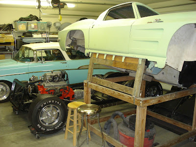
And finally, Max H. likes an occasional big picture of what's going on in the garage so here you go Max...  Enjoy!


Friday, October 29, 2010

327 - HOME RUN! Our 1963 327 FI Corvette Engine Sounds Awesome!

After weeks of frustration we finally got our 1963 327 fuel injected engine to run on its own.  We are extremely excited and we love the way it sounds.  It's awesome!

ORIGINAL FOOTAGE OF THE FIRST SUCCESSFUL START


ADDITIONAL FOOTAGE

Note:  I wasn't able to download the audio file mentioned in the second video.  This blog does not accept that audio file type.

MYSTERY SOLVED - IT WAS THE HIGH PRESSURE FUEL PUMP

I spoke with Gary Hodges yesterday.  Gary is one of just a few people that really know how these mechanical fuel injection units work.  Gary has been dealing with these units for the last 40 years.  Gary sells FI parts and his web page is  http://www.garyhodgesramjet.com/2001.html


I discussed the high pressure fuel pump with Gary and he recommended that I scribe all three main housing pieces before I take the pump apart.  Ty is scribing the fuel pump in this photo. 

Double click on this picture to see the scribe lines.  It's important.

Now, take note of the tiny hole on the end cap near the center of the pump.

This tiny hole is located on the high pressure side of the pump and it shouldn't be there.  When the pump is running the fuel escapes through this hole and goes back into the fuel bowl, not to the injectors.  The end cap had been installed 180 degrees out of position.


This is the correct orientation.  The vent hole is now on the atmosphere side of the pump.  We verified this by examining a picture of an original fuel pump found on Jerry Bramlett's web page.  Check it out here http://www.jerrybramlett.net/museum.html


Note the missing scribe line on the cap.

It's on the opposite side now.  The pump is now assembled properly.

Time to reassemble.

Everything lined up perfectly.

We hooked up the spider and gave the pump a test.  OMG!  We could have drowned in all that fuel!

We were running the drill motor on the lowest speed possible.  Fuel was gushing out like never seen before.  Whoo hoo!


So, what happened next?  Why we grabbed our spouses and celebrated with a little bubbly of course!  Check it out:

Thanks for watching.